_files/carriage%5Br%5D.gif)
_files/carriage%5Bl%5D.gif)
Scale Model Horse Drawn Vehicles
TIPS & IDEAS
|
|
![]()
The aim of the serious model maker is to create an accurate and authentic model in every detail, ideally, to museum standard. There should never be any improvisation or guess work, the model should be a visual three-dimensional historical record. The late David Wray once wrote – “Constructional methods can quite easily follow full sized practice in most cases. I have proved to myself that it is really easier to build a miniature wheel by following wheelwrights methods than to fiddle about with ‘bodge-up methods. Not only is the effect better but one has the satisfaction on knowing that the job has been done properly.”
Ivan Collins who died in 1971, managed to document and build a collection of sixty-three superb models between 1937 and 1970. These are now in the collection of the Oregon Historical Society in Portland. Collins’ made specially built machines and jigs; he even had a small water trough for shrinking the heated tires to the authentically made wheel. Such dedication to detail will result in a model that is a joy to behold.
![]()
If you have any tips or ideas that you would like to share please e-mail them to me, including scanned drawings and photographs. I will then include them in this page.
![]()
![]() The Real Thing If it is practically possible, make a special journey to see the actual
The Real Thing If it is practically possible, make a special journey to see the actual _files/62_530.jpg) model you intend to make. Many rural life museums have been established in recent years and
an incredible variety of the old horse
drawn implements such as ploughs, cultivators, seed drills and hay rakes
etc are on display along with many
carts and waggons. London has a number of horse drawn vehicles in the Science
Museum and the London Transport Museum
has a superb Garden Seat Omnibus. The Reading Borough has a Ledge Caravan.
It is perhaps wise to telephone or
write before
you make the journey as some of them are not on permanent public display.
Take a camera, a sketch pad and tape with you and
get permission before taking photograph and measurements. The
picture to the right is of a Cornish Waggon Built by Aaron Vosper of North
Hill,
near Callington, and owned by Mr Henwood of Linkinhorne, Cornwall. The waggon
is now part of an extensive collection at The Museum of English Rural Life,
The University of Reading, UK. Although many of the objects in the collection
are on display in the public galleries, if you are interested in a particular
topic, you will need to arrange an appointment if you want to view objects
in the reserve collection. It is worth searching the internet as there are a number of very interesting sources in many other countries that house collections of Horse Drawn Vehicles. In the USA there is - The Carriage Association of America and The Henry Ford Museum, in Australia there is The Cobb & Co. Museum; to name but three.
model you intend to make. Many rural life museums have been established in recent years and
an incredible variety of the old horse
drawn implements such as ploughs, cultivators, seed drills and hay rakes
etc are on display along with many
carts and waggons. London has a number of horse drawn vehicles in the Science
Museum and the London Transport Museum
has a superb Garden Seat Omnibus. The Reading Borough has a Ledge Caravan.
It is perhaps wise to telephone or
write before
you make the journey as some of them are not on permanent public display.
Take a camera, a sketch pad and tape with you and
get permission before taking photograph and measurements. The
picture to the right is of a Cornish Waggon Built by Aaron Vosper of North
Hill,
near Callington, and owned by Mr Henwood of Linkinhorne, Cornwall. The waggon
is now part of an extensive collection at The Museum of English Rural Life,
The University of Reading, UK. Although many of the objects in the collection
are on display in the public galleries, if you are interested in a particular
topic, you will need to arrange an appointment if you want to view objects
in the reserve collection. It is worth searching the internet as there are a number of very interesting sources in many other countries that house collections of Horse Drawn Vehicles. In the USA there is - The Carriage Association of America and The Henry Ford Museum, in Australia there is The Cobb & Co. Museum; to name but three.
![]()
![]() Miniature Hinges Many horse drawn vehicles, especially the commercial vehicles, carriages
Miniature Hinges Many horse drawn vehicles, especially the commercial vehicles, carriages_files/Copy%20of%20crop2.jpg) and coaches have doors that open on metal hinges. The American Curtain Rockaway (for instance) has eight hinges, and the smallest, (at 1/8th scale) is 1/8” x 3/16” – not much bigger than the head of a match! You won’t find hinges this small in any of the craft outlets; even dolls house and small trinket box hinges are too big. By far the best way to get the correct scale hinges is to make them yourself. This is not at all difficult, and the materials with which to make them are easily obtainable, and cost very little. Dressmakers Pins have a diameter of about 0.65mm ( 0.025”) and these are ideal to use. You will also require thin sheet metal (tin). Use the tin from an empty beer or larger can, or from a small tin of cat/dog food. Alternatively, you can get the equivalent brass/copper sheet and rod from some model engineering suppliers. The thickness can vary between 0.30mm to 0.50mm (.012” to .020”) and you will find what is best suited for your needs. Cut a strip of tin just a little over 1” wide and no more than 3” long and fold both 1” ends over a dressmakers pin. (fig.1). Crimp the folded tin tight up to the pin using a smooth jawed vice, pliers, or the back end of a table knife. You can then score along the folded piece of tin tight up against the pin with a scriber or a sturdy craft knife, the excess tin will then easily come away by bending a few times. (fig.2). The next stage is to cut out the slots, either with a Swiss file, a razor saw, or a slitting saw. Hold the folded tin, (with the pin still intact, this will help prevent the hinge hole closing up when cutting the slots ) between two pieces of wood, making a slot about 1/16” from the top of one piece so that the whole is held secure and no part of the would-be hinge is standing proud. As dressmakers pins are hardened and tempered it is best to anneal the pin you are going to cut through. If you have a milling machine or can adapt a lathe to take a HSS slitting saw then you can cut quite a number of accurate slots in a very short time and have any number of well made scale hinges. You can get dressmakers pins 30mm (1.18”) long and if you use a slitting saw with a thickness of about 1.14mm (.045”) – making each stand up pieces of the hinge a little smaller than the slot then you will get about 12 slots in each 1” length, as shown here.
and coaches have doors that open on metal hinges. The American Curtain Rockaway (for instance) has eight hinges, and the smallest, (at 1/8th scale) is 1/8” x 3/16” – not much bigger than the head of a match! You won’t find hinges this small in any of the craft outlets; even dolls house and small trinket box hinges are too big. By far the best way to get the correct scale hinges is to make them yourself. This is not at all difficult, and the materials with which to make them are easily obtainable, and cost very little. Dressmakers Pins have a diameter of about 0.65mm ( 0.025”) and these are ideal to use. You will also require thin sheet metal (tin). Use the tin from an empty beer or larger can, or from a small tin of cat/dog food. Alternatively, you can get the equivalent brass/copper sheet and rod from some model engineering suppliers. The thickness can vary between 0.30mm to 0.50mm (.012” to .020”) and you will find what is best suited for your needs. Cut a strip of tin just a little over 1” wide and no more than 3” long and fold both 1” ends over a dressmakers pin. (fig.1). Crimp the folded tin tight up to the pin using a smooth jawed vice, pliers, or the back end of a table knife. You can then score along the folded piece of tin tight up against the pin with a scriber or a sturdy craft knife, the excess tin will then easily come away by bending a few times. (fig.2). The next stage is to cut out the slots, either with a Swiss file, a razor saw, or a slitting saw. Hold the folded tin, (with the pin still intact, this will help prevent the hinge hole closing up when cutting the slots ) between two pieces of wood, making a slot about 1/16” from the top of one piece so that the whole is held secure and no part of the would-be hinge is standing proud. As dressmakers pins are hardened and tempered it is best to anneal the pin you are going to cut through. If you have a milling machine or can adapt a lathe to take a HSS slitting saw then you can cut quite a number of accurate slots in a very short time and have any number of well made scale hinges. You can get dressmakers pins 30mm (1.18”) long and if you use a slitting saw with a thickness of about 1.14mm (.045”) – making each stand up pieces of the hinge a little smaller than the slot then you will get about 12 slots in each 1” length, as shown here. ![]() Then if you cut six pieces from the strip like this,
Then if you cut six pieces from the strip like this, ![]() you can make 3 hinges. Poke out the pieces of cut annealed pin and replace with a new pin cut to length and you have your hinge.
you can make 3 hinges. Poke out the pieces of cut annealed pin and replace with a new pin cut to length and you have your hinge.
![]()
![]() Miniature Chains.“Radish” lives in Brisbane, Australia, and is a model maker of highly detailed 1/12th. Scale Model Horse Drawn Vehicles, (See Model Gallery page) Here he gives a detailed account of the making of scale model chain.....When they were younger my daughters
Miniature Chains.“Radish” lives in Brisbane, Australia, and is a model maker of highly detailed 1/12th. Scale Model Horse Drawn Vehicles, (See Model Gallery page) Here he gives a detailed account of the making of scale model chain.....When they were younger my daughters _files/320bottom.jpg) liked to buy junk jewellery, lots of bits with chains, that had the correct shaped link that I needed, suddenly these bits of jewellery disappeared, out to the shed and into my toolbox! Check out the junk jewellery stands at markets and car boot sales for the correct sized/shaped link chains that you require. I actually haunt the second hand shops for them as well as any other place that might be a good source of chain. There is still a lot of chain made with the correct shape link and to scale as well that is available. I have made link chain as well. (Sometimes you just can’t get the correct size chain you want for your model). To do this, I used a three inch nail as the form tool and file it to the shape of the inside of the chain link. Put a saw cut into the end of the nail and then get some K & S brass wire of the thickness required. Placed one end of the wire into the cut end of the nail, and then secured the nail into a large bench vice, pinching the end of the brass wire sticking out of the nail. This way ALL is secure and tight, then start winding the brass wire around the shaped nail, making sure that the wire is very tight on the nail, use a pair of pliers that DO NOT have ridges on the jaws (or you will mark the brass wire), pinch the wire tight to the nail and keep winding the wire onto the nail. Wind it as many times as the number of links you will require. When you have wound on as much as you can, remove the wound coil from the nail. Use a JEWELLERS SAW to cut the links apart. Do be very careful with each link, as these little blighters can and will disappear to all corners of the workshop and will never reappear again! You now have a bunch of links that you can join together, just open each new link and then add another, crimp the last link back to the required shape and just keep adding until you have the length of chain that you need. Check out the model cannon above and take a good look at the brass chain on the cannon, this was the only way that I could get brass chain of that link size, it works, it's not that hard to do it this way either.If you need chain that is STRONG, as well as to scale, make the chain as above or check out a piece of junk jewellery chain that you may want to use with the soldering iron, if it doesn’t melt when you hit it with the hot iron and it can take soft solder, you’re in luck. Use a very fine tipped electric soldering iron, make sure that it is 40 watt or better, as you need to get each link joint as hot as you can, as quick as you can, without melting the previous link that you have already soldered. The solder that I use is a 5 core, 0.8 mm thick, see the link
here. Use a sharp knife and cut this solder into small bits about 1.00 mm to 1.5 mm long, use a sharp bit of stainless to prick these little bits of solder, (hot solder does not stick to well to stainless) and when you have the link heated up, just dab on the little bit of solder. Doing it this way you limit the amount of solder that can run to the link, virtually no mess to clean up at all, just a quick rub down with a BRASS wire brush and you have a length of clean brass chain that you need, ready for painting or blackening. The solder does not take to the blackening process to well; you can still see the solder joint after you have blackened it. With a little bit of practice though using the minimum amount of solder this can be hardly noticeable. If you want to, you could get your fabricated parts copper plated. Doing as described above you can have a chain knocked up in an evening. ~Radish.~
liked to buy junk jewellery, lots of bits with chains, that had the correct shaped link that I needed, suddenly these bits of jewellery disappeared, out to the shed and into my toolbox! Check out the junk jewellery stands at markets and car boot sales for the correct sized/shaped link chains that you require. I actually haunt the second hand shops for them as well as any other place that might be a good source of chain. There is still a lot of chain made with the correct shape link and to scale as well that is available. I have made link chain as well. (Sometimes you just can’t get the correct size chain you want for your model). To do this, I used a three inch nail as the form tool and file it to the shape of the inside of the chain link. Put a saw cut into the end of the nail and then get some K & S brass wire of the thickness required. Placed one end of the wire into the cut end of the nail, and then secured the nail into a large bench vice, pinching the end of the brass wire sticking out of the nail. This way ALL is secure and tight, then start winding the brass wire around the shaped nail, making sure that the wire is very tight on the nail, use a pair of pliers that DO NOT have ridges on the jaws (or you will mark the brass wire), pinch the wire tight to the nail and keep winding the wire onto the nail. Wind it as many times as the number of links you will require. When you have wound on as much as you can, remove the wound coil from the nail. Use a JEWELLERS SAW to cut the links apart. Do be very careful with each link, as these little blighters can and will disappear to all corners of the workshop and will never reappear again! You now have a bunch of links that you can join together, just open each new link and then add another, crimp the last link back to the required shape and just keep adding until you have the length of chain that you need. Check out the model cannon above and take a good look at the brass chain on the cannon, this was the only way that I could get brass chain of that link size, it works, it's not that hard to do it this way either.If you need chain that is STRONG, as well as to scale, make the chain as above or check out a piece of junk jewellery chain that you may want to use with the soldering iron, if it doesn’t melt when you hit it with the hot iron and it can take soft solder, you’re in luck. Use a very fine tipped electric soldering iron, make sure that it is 40 watt or better, as you need to get each link joint as hot as you can, as quick as you can, without melting the previous link that you have already soldered. The solder that I use is a 5 core, 0.8 mm thick, see the link
here. Use a sharp knife and cut this solder into small bits about 1.00 mm to 1.5 mm long, use a sharp bit of stainless to prick these little bits of solder, (hot solder does not stick to well to stainless) and when you have the link heated up, just dab on the little bit of solder. Doing it this way you limit the amount of solder that can run to the link, virtually no mess to clean up at all, just a quick rub down with a BRASS wire brush and you have a length of clean brass chain that you need, ready for painting or blackening. The solder does not take to the blackening process to well; you can still see the solder joint after you have blackened it. With a little bit of practice though using the minimum amount of solder this can be hardly noticeable. If you want to, you could get your fabricated parts copper plated. Doing as described above you can have a chain knocked up in an evening. ~Radish.~
![]() Trains & Boats & Planes.Whether you are a newcomer to the h
Trains & Boats & Planes.Whether you are a newcomer to the h_files/2x2.jpg) obby of Scale Model Horse Drawn Vehicles or an ‘old hand’ you will find very few (if any!) businesses, suppliers or companies who cater solely for the SMHDV enthusiast. The same can be said of web sites, related forums and publications. The model steam locomotive devotee is well catered for, as is the jewellery maker and the radio controlled model aficionado. So where, you may ask, does that leave the SMHDV enthusiast? Well, as a matter of fact, it leaves him/her in a very good position indeed! All, (or mostly all) of the tools, materials and know-how required can be obtained from suppliers and companies that cater for the vast number of other hobbies and small businesses. First and foremost of course are the model engineering suppliers. You can get milling machines, lathes, bench grinders, drill presses, brazing/soldering hearths, and band saws etc. with all the associated accessories to go with them. You can also get an almost infinite selection of materials and tools from model engineering suppliers. There are many other outlets where tools, materials and ideas can be had. Look at the model boat and plane web sites, scale military vehicles, diorama and figures may give you a hint of an idea that would be useful to you. A really great site is that of Gerald Wingroves, a superb craftsman and Model Engineer who makes 1/20th and 1/15th scale fully detailed miniature automobiles. Just looking at the fine detail of engine parts and chassis in the extensive gallery section should convince any model maker that the soldering and assembly of miniature metal parts should never be a difficult or daunting prospect. I believe Gerald has recently made a number of HDV plans available in 1/15th scale! So as you can see, the information and whereabouts of ideas, tools and materials can be got from a number of un-lightly sources. Clock makers, jewellers and craft suppliers etc.; it only requires a little diligent searching.
obby of Scale Model Horse Drawn Vehicles or an ‘old hand’ you will find very few (if any!) businesses, suppliers or companies who cater solely for the SMHDV enthusiast. The same can be said of web sites, related forums and publications. The model steam locomotive devotee is well catered for, as is the jewellery maker and the radio controlled model aficionado. So where, you may ask, does that leave the SMHDV enthusiast? Well, as a matter of fact, it leaves him/her in a very good position indeed! All, (or mostly all) of the tools, materials and know-how required can be obtained from suppliers and companies that cater for the vast number of other hobbies and small businesses. First and foremost of course are the model engineering suppliers. You can get milling machines, lathes, bench grinders, drill presses, brazing/soldering hearths, and band saws etc. with all the associated accessories to go with them. You can also get an almost infinite selection of materials and tools from model engineering suppliers. There are many other outlets where tools, materials and ideas can be had. Look at the model boat and plane web sites, scale military vehicles, diorama and figures may give you a hint of an idea that would be useful to you. A really great site is that of Gerald Wingroves, a superb craftsman and Model Engineer who makes 1/20th and 1/15th scale fully detailed miniature automobiles. Just looking at the fine detail of engine parts and chassis in the extensive gallery section should convince any model maker that the soldering and assembly of miniature metal parts should never be a difficult or daunting prospect. I believe Gerald has recently made a number of HDV plans available in 1/15th scale! So as you can see, the information and whereabouts of ideas, tools and materials can be got from a number of un-lightly sources. Clock makers, jewellers and craft suppliers etc.; it only requires a little diligent searching.
![]()
![]() Making Scale Coach Bolts.Here is another invaluable tip from “Radish”; on how to make scale coach bolts. Here is a way of making scale bolts from an Escutchion Nail/P
Making Scale Coach Bolts.Here is another invaluable tip from “Radish”; on how to make scale coach bolts. Here is a way of making scale bolts from an Escutchion Nail/P_files/es-pin.JPG) in. These nails can be put to good use by turning them into scale coach bolts. They are normally made from brass and are available at most hardware stores. You can get them in a couple of different shank diameters which are suitable for 8BA, 2mm and 10BA in quite an assortment of lengths as well. To put a thread on these little fellas is as easy as using a thread die of the appropriate size required. You only need to be able to hang on to them whilst threading them. Get a piece of 1/8th plate and cut it to 40mm long by 30mm wide, in one end, drill a hole the same size as the pin, the other end drill a 6 or 8mm and then with a thin saw, cut all the way from the small hole to the larger hole, see Fig 1. Insert the pin into the smaller hole and then clamp this lot into the jaws of a vice, you can now put a hell of a lot of pressure on the shank of the pin and thread away to your hearts desire!....... see Fig 2.
in. These nails can be put to good use by turning them into scale coach bolts. They are normally made from brass and are available at most hardware stores. You can get them in a couple of different shank diameters which are suitable for 8BA, 2mm and 10BA in quite an assortment of lengths as well. To put a thread on these little fellas is as easy as using a thread die of the appropriate size required. You only need to be able to hang on to them whilst threading them. Get a piece of 1/8th plate and cut it to 40mm long by 30mm wide, in one end, drill a hole the same size as the pin, the other end drill a 6 or 8mm and then with a thin saw, cut all the way from the small hole to the larger hole, see Fig 1. Insert the pin into the smaller hole and then clamp this lot into the jaws of a vice, you can now put a hell of a lot of pressure on the shank of the pin and thread away to your hearts desire!....... see Fig 2.
And if you need a longer bolt..........
You need a bolt that is longer than what you have, you only need a bit of brass rod of the appropriate diameter that the thread requires. So you need a two mm bolt that is about 50mm long, just put a thread on each end of the 50mm long x 2mm brass rod and add a nut to one end, then soft solder the nut in place and then shape the nut with a file to look like the head of a coach bolt, instant long bolts. The brass to use here is available at just about ALL hobby shops, just ask for K & S Brass and Aluminium bits, the K & S brass that is in these stands is a ‘hard’ brass and can be threaded or tapped relatively easily. It comes in a multitude of diameters and there is one for 8BA, 10BA, 12BA, 3mm and 2mm. The other alternative is to thread the whole length of brass rod and just cut of what lengths you require. Another material to use for miniature bolts is Bronzing rod, this material is a dream to cut with the lathe and takes a thread very easily, it is available in different diameters and can be picked up at any welding suppliers. It is also a lot cheaper than using K & S brass rods, K & S is about Aust $4 a foot, bronzing rod is about Aust $0.50c per foot, a big difference in price, so I use the bronzing rod ALL the time, it’s a bit stronger than brass as well. ~Radish.~
![]() Jigs, Tools & Fixtures.
Jigs, Tools & Fixtures. _files/4x4jig.JPG) When assembling and holding the various component of your model secure and ensuring you have precise alignment you will find work-saving jigs and tools a considerable help in achieving the best results. These jigs can be made from a variety of materials, wood, metal, plastic, and often these can be combined to create a more elaborate and stable fixture. Sometimes, something simple like a few elastic-bands, screws, paper-clips or masking-tape may be all that is required to secure the parts that require drilling, cutting, gluing or soldering etc. Very often, an effective work-saving jig, fixture or tool can be crude and simple, at other times it may be an elaborate and more complex set-up. The dividing lines among these devices are often hard to define and imprecise, but as long as it is capable of doing the job, then that is all that is needed. Various tools, locking clamps, pliers and tweezers can be bought and sometimes two or more of these can themselves be fixed to a piece of wood, metal or work bench to make a more elaborate jig or fixture. The four pictures on the left show just some of these tools and clamps that are available from suppliers. The top left picture shows a jig used for bending wire and small metal strip; the small steel pins can be moved to different locations in the cast aluminium block to achieve the shape you need. You can of course make your own wire bending jig from wood or steel to suite whatever shape and size you require. The picture top right shows a modular work holder. There are 3 articulated arms….two with alligator clips and one with a long-nose self-closing tweezer, which holds the work steady and in the perfect position for assembly, soldering and painting. You could perhaps rig up something similar using alligator clips held in place by a piece of Plasticine.
When assembling and holding the various component of your model secure and ensuring you have precise alignment you will find work-saving jigs and tools a considerable help in achieving the best results. These jigs can be made from a variety of materials, wood, metal, plastic, and often these can be combined to create a more elaborate and stable fixture. Sometimes, something simple like a few elastic-bands, screws, paper-clips or masking-tape may be all that is required to secure the parts that require drilling, cutting, gluing or soldering etc. Very often, an effective work-saving jig, fixture or tool can be crude and simple, at other times it may be an elaborate and more complex set-up. The dividing lines among these devices are often hard to define and imprecise, but as long as it is capable of doing the job, then that is all that is needed. Various tools, locking clamps, pliers and tweezers can be bought and sometimes two or more of these can themselves be fixed to a piece of wood, metal or work bench to make a more elaborate jig or fixture. The four pictures on the left show just some of these tools and clamps that are available from suppliers. The top left picture shows a jig used for bending wire and small metal strip; the small steel pins can be moved to different locations in the cast aluminium block to achieve the shape you need. You can of course make your own wire bending jig from wood or steel to suite whatever shape and size you require. The picture top right shows a modular work holder. There are 3 articulated arms….two with alligator clips and one with a long-nose self-closing tweezer, which holds the work steady and in the perfect position for assembly, soldering and painting. You could perhaps rig up something similar using alligator clips held in place by a piece of Plasticine.
I think the most essential jig or set-up when taking on the task of building a model is what I would_files/asambord.JPG) loosely refer to as the ‘Assembly Board.’ The novice SMHDV builder will find very little advice or detailed instructions, from the majority of the plans that are available, in putting together all the timber and metal parts that make up a detailed model. So what then do we use as the Assembly Board? A thick piece of ply-wood or a piece of M.D.F. (Medium Density Fibreboard), which should be a bit bigger than the length and width of the model, is ideal. You will need a number of pieces of your model from which to start building from. This could be the axle-bed timbers, the bolsters, the summers or, (in the case of something like The Cowboy "Chuck" Waggon – which has a flat box shape), the body of the model. Let us say, for example, that you are building up from the axle-bed timbers. You would then fix these firmly to the Assembly Board, at the correct distance from each other, parallel and flat to the board, using a scrap-wood spacer (the correct thickness) to lift the rear axle-bed timber higher than the front. The very rudimentary drawing shown above right, goes a little way in showing how the Assembly Board set up is put into practice. If you wanted to assemble your model from the summers and/or side timbers you could fix scrap pieces of timber with correctly spaced and shaped slots to hold the curved and irregularly shaped summers. So whatever model you are making, and whatever parts you wish to start assembling from, a bit of thought and planning on how you can best achieve this will go a long way in making things easer and finishing with a model you can be proud of! There are a number of advantages in using the Assembly Board. You can turn the whole thing round and work from the other side without disturbing what you have already done. You can move it off your work bench to a safer place if you have to leave it a day or two before completion; or if you need the work bench space for some other project. And finally, everything should be easer to line up and make square and equal if you have set everything up correctly and securely from the start. Look at some of the other jigs and tools that are shown and described in the ‘Tips & Ideas’ pages. Making miniature hinges, miniature chain, scale coach bolts and scale wheels are all made using some form of jig or tool. Sometimes a bit of lateral thinking will result in coming up with a great idea! ... So get thinking! Get your ideas and tips, and your work-saving jigs on this page.
loosely refer to as the ‘Assembly Board.’ The novice SMHDV builder will find very little advice or detailed instructions, from the majority of the plans that are available, in putting together all the timber and metal parts that make up a detailed model. So what then do we use as the Assembly Board? A thick piece of ply-wood or a piece of M.D.F. (Medium Density Fibreboard), which should be a bit bigger than the length and width of the model, is ideal. You will need a number of pieces of your model from which to start building from. This could be the axle-bed timbers, the bolsters, the summers or, (in the case of something like The Cowboy "Chuck" Waggon – which has a flat box shape), the body of the model. Let us say, for example, that you are building up from the axle-bed timbers. You would then fix these firmly to the Assembly Board, at the correct distance from each other, parallel and flat to the board, using a scrap-wood spacer (the correct thickness) to lift the rear axle-bed timber higher than the front. The very rudimentary drawing shown above right, goes a little way in showing how the Assembly Board set up is put into practice. If you wanted to assemble your model from the summers and/or side timbers you could fix scrap pieces of timber with correctly spaced and shaped slots to hold the curved and irregularly shaped summers. So whatever model you are making, and whatever parts you wish to start assembling from, a bit of thought and planning on how you can best achieve this will go a long way in making things easer and finishing with a model you can be proud of! There are a number of advantages in using the Assembly Board. You can turn the whole thing round and work from the other side without disturbing what you have already done. You can move it off your work bench to a safer place if you have to leave it a day or two before completion; or if you need the work bench space for some other project. And finally, everything should be easer to line up and make square and equal if you have set everything up correctly and securely from the start. Look at some of the other jigs and tools that are shown and described in the ‘Tips & Ideas’ pages. Making miniature hinges, miniature chain, scale coach bolts and scale wheels are all made using some form of jig or tool. Sometimes a bit of lateral thinking will result in coming up with a great idea! ... So get thinking! Get your ideas and tips, and your work-saving jigs on this page.
![]()
![]() Making Scale Wheels. I am most indebted to “Radish” a master model maker who lives in Brisbane, Australia for his valued input into the Tips & Ideas page. Even other experienced model makers will, I am sure, benefit from his knowledge and experience and admire his detailed models. Here he shares his know-how on making scale model wheels. .Click here for a detailed account on how to construct 'Sarven' type wheels.
Making Scale Wheels. I am most indebted to “Radish” a master model maker who lives in Brisbane, Australia for his valued input into the Tips & Ideas page. Even other experienced model makers will, I am sure, benefit from his knowledge and experience and admire his detailed models. Here he shares his know-how on making scale model wheels. .Click here for a detailed account on how to construct 'Sarven' type wheels.
When other people are looking at a model of a horse drawn vehicle that you have made, the first thing that they will notice wrong with the model, is, ‘if' the wheels have not been made correctly, they will definitely tell you that the _files/tandi%20009.jpg) wheels are wrong. The easiest cure for this is to make the wheels as close to correct, as you possibly can. You ‘can’ try and make them exactly the same as a wheelwright makes them, this is a bit tricky when you are working to a smaller scale, the tang on the end of the spoke can be only a couple of millimetres in diameter. You can, and will, break these little tangs of the spoke ends, if you try and FORCE the tangs into the felloes. If you can make them this way, good luck to you and you don’t need to read any further. A model wheel, made in a very similar fashion to the way a wheelwright makes a wheel, can look just as good and is quite a bit easier to make as well. If you are already making model horse drawn vehicles (MHDV), then you should have heard of a gentleman called John Thompson. He has had a number of books published on the subject of MHDV. The only book by John Thomson that I have, is called Making Model Gypsy Caravans, he goes into great detail on how to make the wheels for the model of the Gypsy Caravan with drawings included in this explanation. It is well worth the effort to get hold of this particular publication if you can. Another excellent book to acquire is The Secrets of Wheelwrighting ‘TYRES’ by a Mr M.C. Hendrikson, a wheelwright, coachbuilder and blacksmith – ISBN 0646312014. Mike Hendrikson helped to create Old Sydney Town, which is Nth of Sydney, New South Wales; he then went to Victoria and helped create Sovereign Hill at Ballarat in Victoria, Australia. This book is a very down to earth, easily understood publication, if you can get hold of it, then do so!
wheels are wrong. The easiest cure for this is to make the wheels as close to correct, as you possibly can. You ‘can’ try and make them exactly the same as a wheelwright makes them, this is a bit tricky when you are working to a smaller scale, the tang on the end of the spoke can be only a couple of millimetres in diameter. You can, and will, break these little tangs of the spoke ends, if you try and FORCE the tangs into the felloes. If you can make them this way, good luck to you and you don’t need to read any further. A model wheel, made in a very similar fashion to the way a wheelwright makes a wheel, can look just as good and is quite a bit easier to make as well. If you are already making model horse drawn vehicles (MHDV), then you should have heard of a gentleman called John Thompson. He has had a number of books published on the subject of MHDV. The only book by John Thomson that I have, is called Making Model Gypsy Caravans, he goes into great detail on how to make the wheels for the model of the Gypsy Caravan with drawings included in this explanation. It is well worth the effort to get hold of this particular publication if you can. Another excellent book to acquire is The Secrets of Wheelwrighting ‘TYRES’ by a Mr M.C. Hendrikson, a wheelwright, coachbuilder and blacksmith – ISBN 0646312014. Mike Hendrikson helped to create Old Sydney Town, which is Nth of Sydney, New South Wales; he then went to Victoria and helped create Sovereign Hill at Ballarat in Victoria, Australia. This book is a very down to earth, easily understood publication, if you can get hold of it, then do so!
In making model wheels I follow the method described by John T_files/naves.jpg) homson as I have found it to work very well for me. (Figure 1.) It is not the only way to make a model wheel, there are other people who have their way of doing it, and their end results can be equaly as successful. Before I set out to make any wheels, I draw them to scale size first, to see if there will be any problems, I include every detail that I need to onto these drawings, and then use the drawings to make the wheels. This is my way of knowing that the finished model wheels will look correct. Wheels for different vehicles are totally different in design to each other, so a wheel for a buggy will not suit a wagon at all. That is why I draw each of them, to make sure that it all works out. The timber I use for my models is called Tasmanian Myrtle—Nothofagus Cunninghamii – it is excellent for models as it is a hard wood, with very, very small pore holes and this timber can be turned, sawn, carved, sanded, cut and drilled (did I miss anything there?) When painting this timber, no grain stands up with the first coat of paint, so, no need to sand between coats of paint, and it takes a coat of paint as though it were sheet polystyrene that you are painting. Painting is another subject, so won’t go into any detail here.
homson as I have found it to work very well for me. (Figure 1.) It is not the only way to make a model wheel, there are other people who have their way of doing it, and their end results can be equaly as successful. Before I set out to make any wheels, I draw them to scale size first, to see if there will be any problems, I include every detail that I need to onto these drawings, and then use the drawings to make the wheels. This is my way of knowing that the finished model wheels will look correct. Wheels for different vehicles are totally different in design to each other, so a wheel for a buggy will not suit a wagon at all. That is why I draw each of them, to make sure that it all works out. The timber I use for my models is called Tasmanian Myrtle—Nothofagus Cunninghamii – it is excellent for models as it is a hard wood, with very, very small pore holes and this timber can be turned, sawn, carved, sanded, cut and drilled (did I miss anything there?) When painting this timber, no grain stands up with the first coat of paint, so, no need to sand between coats of paint, and it takes a coat of paint as though it were sheet polystyrene that you are painting. Painting is another subject, so won’t go into any detail here.
Along with making the wheels is the axle, I use “ key steel “ for _files/spokes.jpg) this, as it has the strength that is required and the size range of key steel is suited to the 1/12 th scale that I work with. I draw the axle to scale and then proceed to make the axle first; this then allows me to start making the hub/nave. Roughly cut out the nave/hub as a rectangle which is oversize on a bandsaw or bench saw and then into the four jaw chuck on the lathe, I use a Unimat 3 for most bits that need to be turned. Drill a hole down the centre of the timber so a brass axle box can be glued into place. I use brass as it is easy to turn and is cheap, but most importantly, it can not adhere/rust to the key steel axle, the wheel on the model will still be able to turn around quite easily, ten years later, with no problems at all. This then enables the nave/hub to be held by a SMALL MANDREL that is the same as the end of the axle.
this, as it has the strength that is required and the size range of key steel is suited to the 1/12 th scale that I work with. I draw the axle to scale and then proceed to make the axle first; this then allows me to start making the hub/nave. Roughly cut out the nave/hub as a rectangle which is oversize on a bandsaw or bench saw and then into the four jaw chuck on the lathe, I use a Unimat 3 for most bits that need to be turned. Drill a hole down the centre of the timber so a brass axle box can be glued into place. I use brass as it is easy to turn and is cheap, but most importantly, it can not adhere/rust to the key steel axle, the wheel on the model will still be able to turn around quite easily, ten years later, with no problems at all. This then enables the nave/hub to be held by a SMALL MANDREL that is the same as the end of the axle.
ALL operations on the nave/hub are now carried out with it mounted on this mandrel; this then enables the wheel to run true throughout its manufacture, therefore, four wheels, and four mandrels, one for each wheel. By not using four mandrels, you are risking that the wheels will not run true when you are finished, the choice is yours. After fitting the axle boxes, then start on the shape of the hub/nave, you can turn them freehand if you are lucky or a skilled lathe operator, or you can make up a pattern, to be able to plunge cut to a pre-set depth, this will get the hubs/nave as close as possible to each other. This pattern can be made out _files/felloes.jpg) of a piece of 1/8 th steel plate and hand filed to the required shape. Normally on a four wheel vehicle, the two front wheel naves will be slightly smaller than the back wheels naves, so two patterns are required for a four wheel vehicle. By making them out of a rather thin bit of steel, you are risking that these patterns can be bent if you jamb them into the nave too hard, so very easy with this operation, you only have to scratch away at the naves until they are both the same, use light cuts and the patterns will survive. Use the patterns on the hub as the LAST part of the cutting operation, rough the naves down to a circular piece somewhere near the finished shape required before using the patterns, remember that the patterns do not like square corners at all. When you’re finished with the pattern tool, get out some wet & dry, 360 grade and give it a very light sand until it looks and feels silky smooth. Once all the naves are to the correct shape/size, you can fit the nave bands if you require them to be fitted. Then an easy set-up in the Uni 3 for milling out the spacings so the spokes can to be fitted to the nave, I then follow this up with a chisel, that has been made from a 1/8 th drill, to square of/out the rounded milled spoke holes. (Figure 2.)
of a piece of 1/8 th steel plate and hand filed to the required shape. Normally on a four wheel vehicle, the two front wheel naves will be slightly smaller than the back wheels naves, so two patterns are required for a four wheel vehicle. By making them out of a rather thin bit of steel, you are risking that these patterns can be bent if you jamb them into the nave too hard, so very easy with this operation, you only have to scratch away at the naves until they are both the same, use light cuts and the patterns will survive. Use the patterns on the hub as the LAST part of the cutting operation, rough the naves down to a circular piece somewhere near the finished shape required before using the patterns, remember that the patterns do not like square corners at all. When you’re finished with the pattern tool, get out some wet & dry, 360 grade and give it a very light sand until it looks and feels silky smooth. Once all the naves are to the correct shape/size, you can fit the nave bands if you require them to be fitted. Then an easy set-up in the Uni 3 for milling out the spacings so the spokes can to be fitted to the nave, I then follow this up with a chisel, that has been made from a 1/8 th drill, to square of/out the rounded milled spoke holes. (Figure 2.)
The spokes are made with a bandsaw fol_files/jig%20for%20turning%20felloes%20jig.jpg) lowed by a touch up in a thickness sander, to get the thickness required, then onto a small bench saw to be cut into strips and then back to the thickness sander for final sizing. This allows me to be able to make as many lengths of spoke material as I require. I then hand shape the spokes with a file and a quick sand/rub down with 360 wet & dry to remove any blemishes and then trim them to the correct length. Followed by using a jig I made for the lathe, to be able to get the correct angle onto the square end of the spoke that is going to be driven into the nave. (Figure 3.)This way I can then be assured of having the right/correct amount of dish, built into each wheel. All wheels have dish built into them for strength and the dish will correspond with the tilt/bend in the axle end. This is one of the reasons that I draw all the details, to be able to get all this correct. Then into another jig to be able to drive the spokes into the nave, a dab of carpenters glue on the end of the spoke and into the squared out hole on the nave. A couple of light taps from a small hammer to seat each spoke to the axle box and pretty soon you have a spider, put it aside to let everything dry out and tighten up, a couple of days later all will be rock solid.
lowed by a touch up in a thickness sander, to get the thickness required, then onto a small bench saw to be cut into strips and then back to the thickness sander for final sizing. This allows me to be able to make as many lengths of spoke material as I require. I then hand shape the spokes with a file and a quick sand/rub down with 360 wet & dry to remove any blemishes and then trim them to the correct length. Followed by using a jig I made for the lathe, to be able to get the correct angle onto the square end of the spoke that is going to be driven into the nave. (Figure 3.)This way I can then be assured of having the right/correct amount of dish, built into each wheel. All wheels have dish built into them for strength and the dish will correspond with the tilt/bend in the axle end. This is one of the reasons that I draw all the details, to be able to get all this correct. Then into another jig to be able to drive the spokes into the nave, a dab of carpenters glue on the end of the spoke and into the squared out hole on the nave. A couple of light taps from a small hammer to seat each spoke to the axle box and pretty soon you have a spider, put it aside to let everything dry out and tighten up, a couple of days later all will be rock solid.
The felloes have not been forgotten, they are made as triangular pieces, if making a 14 spoke wheel, therefore seven felloes are required, two spokes to each felloe. So seven sections that look like a slice of pie are cut out, (Figure 4.) then into another jig to be able to sand them, so they are all the same size and shape, to be able to get them to fit together as closely as you can without any gaps, if possible, then glued together and held tight on a board using nails and a tapered chock, to hold everything in place whilst the glue dries. This is where the manufacturing process differs from a wheelwright, as NO tangs on the end of the spokes will be used at all, or dowels, will be fitted between the felloes. This is a model vehicle wheel and will not have to earn its keep out on a rough road or carry anything heavy at all, but will still look like a miniature version of the real thing.
When_files/nap1.jpg) the glue on the felloes segments has dried out, it’s time to make the felloes as a circular piece of seven segments of timber. I make a 12 mm hole in the centre of these glued segments and put a couple of round thick timber washers, one each side of the segmented felloes and all are held tight with a 12mm nut and bolt. (Figure 5.) Then into the chuck of a ‘very old’ Myford lathe, and after a bit of turning you should have this nice ring of segmented pieces all in one circle. A lot of care is required with this part, or the segments will break apart at the glued joints. Start turning the outside diameter first, leave a couple of millimetres up on the O/D, to be turned true later, leave a couple of millimetres on the sides for the same reason, the only dimension that should be correct, is the internal diameter. When all four sets of felloes are turned as you want them, time to get back to the four spiders. I set up the jig, (Figure 6.) which was used when the spokes were driven into the nave, onto the cross-slide of the Uni 3 and use a hollowed out grinding wheel in the chuck. The spider, ( this is a term used to refer to the spokes fixed to the nave before the ring of felloes is attached ) is mounted into the jig at the correct height and then the cross slide is slowly advanced toward the grinding wheel. When the first spoke touches the wheel, start to rotate the spider until all the spokes have touched the grinding wheel. Keep advancing the cross-slide until you can measure the EXACT same measurement, as the inside of the ring of felloes that you are going to fit this particular spider to.
the glue on the felloes segments has dried out, it’s time to make the felloes as a circular piece of seven segments of timber. I make a 12 mm hole in the centre of these glued segments and put a couple of round thick timber washers, one each side of the segmented felloes and all are held tight with a 12mm nut and bolt. (Figure 5.) Then into the chuck of a ‘very old’ Myford lathe, and after a bit of turning you should have this nice ring of segmented pieces all in one circle. A lot of care is required with this part, or the segments will break apart at the glued joints. Start turning the outside diameter first, leave a couple of millimetres up on the O/D, to be turned true later, leave a couple of millimetres on the sides for the same reason, the only dimension that should be correct, is the internal diameter. When all four sets of felloes are turned as you want them, time to get back to the four spiders. I set up the jig, (Figure 6.) which was used when the spokes were driven into the nave, onto the cross-slide of the Uni 3 and use a hollowed out grinding wheel in the chuck. The spider, ( this is a term used to refer to the spokes fixed to the nave before the ring of felloes is attached ) is mounted into the jig at the correct height and then the cross slide is slowly advanced toward the grinding wheel. When the first spoke touches the wheel, start to rotate the spider until all the spokes have touched the grinding wheel. Keep advancing the cross-slide until you can measure the EXACT same measurement, as the inside of the ring of felloes that you are going to fit this particular spider to.
When, this EXACT measurement is achieved, out of the jig with the finished spider. You can now check fit this sized spider to ‘the’ turned segment of felloes, gently squeeze the spokes into the rim being very careful that it does not break apart the felloes, and, if it feels too tight, STOP, or you WILL pop the fellies apart at the glue joints if you keep pushing, so a lot of caution is required when doing this, so as to get everything together without making a mess of it. If too tight, just very lightly sand a very small amount from the ends of ALL the spiders and try again. When the spider fits nicely into the ring of segments, then add a drop of carpenters glue to the ends of each spoke and gently press this lot together again, making sure that the spokes are in the centre/middle of the felloes segments. The rule of thumb here is “MEASURE TWICE, CUT ONCE, get it right and it looks right, do it wrong and everybody will let you know it is wrong. With the felloes segments now firmly glued to the spiders, place the full wheel back into the lathe and you can now turn the felloes to the EXACT size O/D and thickness that is required. By doing it in this order you will now have a miniature wheel that actually runs DEAD TRUE, when fitted onto the axle. The only flaw in this plan is when the tyre is fitted, it will run out very slightly when spun around, but there are ways of getting that lot to run just about true as well, but, fitting the tyre is later. When all is done and you are ready to paint the model/wheels, do so. Add any pin striping or decorations that are required for the wheels and when you are finished ALL the painting, it is time to make the tyre. The tyre actually holds everything together, just like the original wheelwrights method, only this time it is being put on last, as the wheelwright puts the tyre on and then paints the wheel. If you are making the tyre yourself, use some hollow bar mild steel, 10-40 is quite OK and using hollow bar saves a lot of turning as well. Measure the outside diameter of the painted wooden wheel and ATTEMPT to turn the inside diameter of the tyre about a couple of thousands of an inch above the O/D of the wheel, this way you can fit the tyre without squeezing the glued joints of the felloes and forcing glue or paint from the joints. When the tyre can just be squeezed onto the rim and removed, take the steel tyre to a source of heat, I use an electric hotplate stove and heat up the tyre until the steel turns blue, remove it from the heat and w_files/red.jpg) hen cool, rub it down with steel wool on the side that touches the ground, this will give the steel tyre a used look and the sides are still blueish in colour and look like they have been in a blacksmiths forge. Now carefully squeeze the tyre back onto the wooden wheel and if you have done the job right, all is well.
hen cool, rub it down with steel wool on the side that touches the ground, this will give the steel tyre a used look and the sides are still blueish in colour and look like they have been in a blacksmiths forge. Now carefully squeeze the tyre back onto the wooden wheel and if you have done the job right, all is well.
To make the steel tyre run true to the wooden wheel, back into the lathe with the lot still on the mandrel, turn the chuck over by hand and you can now see where the tyre is running out, very carefully push the tyre to adjust the runout, you should be able to get it just about spot-on. Remembering that a wheelwrights/ blacksmiths fitted tyre will NEVER run exactly true, so close enough is good enough here. If it looks right, then it probably is. If there are any spaces between the wooden wheels and the steel tyres, check this by holding the wheel up to a light and looking for any gaps, these can be filled in very easily, make up a thin mixture of carpenters glue and water, dip a fine paint brush into the mix and then dab this mix into the gaps, you might have to do it a few times, but there will be no noticeable gaps when you have finished, any of this mix that you get on the paint can be easily wiped away with a damp cloth. You now should have a set of wheels that look quite right and all wheels should spin very close to true as well, if you can take as much care with the rest of the model whilst you are making it, then this model will be of exceptional quality and a joy to behold. This will now make it very difficult for anybody to criticise the model at all! (Figure 7.)
There are many designs and variations on wheels that it would take a book to list all the details, this is a shortened version of the way that I make this particular type of spoked wheel. If anybody has any queries or wants to direct any form of criticism toward what is written here please feel free to direct ALL to the SMHDV site, where I am sure each and every one of you will be answered. ~Radish.~
Click here for a detailed account on how to construct 'Sarven' type wheels.
![]()
Ron Curzon is a model maker who lives in England and he is a member of 'The Guild of Model Wheelwrights'. Here he describes his method of making the wheels of his detailed models.
Draw or make a template of the spoke and mark out timber,(Pic 1). Turn the naves as usual, index spoke position ready for mortice's, (Pic 2). Draw the wheel full size on a piece of M.D.F.(Medium Density Fibreboard), a bit over sized for truing up, mark out the fellies & spoke positions, then turn a recess, Make a template of the fellows, sand to fit M.D.F. Mark, cut and sand all fellies, keeping fellies to lines, mark spoke position on the fellies then turn the inside Diameter to size, number them in order, so you can get them in the same place, (Pic 3).
Cut and shape spokes, including tennons, mortise naves, test fit spokes,(Pic 4). Drill spoke holes in the fellows, test fit to spokes. When this is done, and every thing fits, glue the spokes in the Naves, place the fellows on loose, and cramp up using this method, (Pic 5). Glue the fellows on last making sure. The finished wheels are shown in (Pic 6), these have staggered spokes, of 1/16 of an inch, 1/2 an inch on the real waggon. ~Ron Curzon.~
_files/pic1.jpg) |
_files/pic2.jpg) |
_files/pic3.jpg) |
_files/pic4.jpg) |
_files/pic5.jpg) |
_files/pic6.jpg) |
![]()
![]() Painting Models.
Painting Models. _files/daylight2.jpg) Look
around the exhibition hall at a Model Engineering Exhibition and you will
find it packed with models, some extremely good, some just good and more than
a few not to good at all! So what is it that makes a model win a coveted gold
or silver medal? It is authenticity, attention to detail, faultless structural
and historical accuracy to the highest standard possible….and of course,
the paint finish! Many a fine model has been spoilt by the paintwork.
Imagine you have spent perhaps a thousand hours on your Ledge Waggon, Garden
Seat Omnibus or American Concord Stagecoach, and now it just needs painting!
If you have never painted a model before and haven’t much of an idea
where to start, then don’t start painting yet! Spend a week or two researching
the subject. The internet is a mine of information and it is worth looking
at various scale modeling sites such as steam locomotives, aircraft, ships
and military figures to name but a few. I have a small 28 page booklet ‘The
Finishing Touch’ by Robert G. Shephard that is over 20 years old. An
updated second edition of the book is available from Phoenix
Precision Paints, and is a MUST for any serious modeler. Any tips or suggestions
given here are from many years of experience, not necessarily my own experience,
but that which has been given by others, in books, and at model shows etc.
You will no doubt learn, (as I did) from the mistakes you make. The pale yellow
colour used for the Ledge Waggon was not directly available from any paint
source, and was attained by mixing yellow and ivory together, (from Phoenix
Precision Paints) in various ratios until the correct colour was achieved.
If you have to do this to get the colour you want then do remember to make
an accurate record of the relative amounts of each, or mix enough first time
to meet your requirements. Always thoroughly mix your paint, vigor
Look
around the exhibition hall at a Model Engineering Exhibition and you will
find it packed with models, some extremely good, some just good and more than
a few not to good at all! So what is it that makes a model win a coveted gold
or silver medal? It is authenticity, attention to detail, faultless structural
and historical accuracy to the highest standard possible….and of course,
the paint finish! Many a fine model has been spoilt by the paintwork.
Imagine you have spent perhaps a thousand hours on your Ledge Waggon, Garden
Seat Omnibus or American Concord Stagecoach, and now it just needs painting!
If you have never painted a model before and haven’t much of an idea
where to start, then don’t start painting yet! Spend a week or two researching
the subject. The internet is a mine of information and it is worth looking
at various scale modeling sites such as steam locomotives, aircraft, ships
and military figures to name but a few. I have a small 28 page booklet ‘The
Finishing Touch’ by Robert G. Shephard that is over 20 years old. An
updated second edition of the book is available from Phoenix
Precision Paints, and is a MUST for any serious modeler. Any tips or suggestions
given here are from many years of experience, not necessarily my own experience,
but that which has been given by others, in books, and at model shows etc.
You will no doubt learn, (as I did) from the mistakes you make. The pale yellow
colour used for the Ledge Waggon was not directly available from any paint
source, and was attained by mixing yellow and ivory together, (from Phoenix
Precision Paints) in various ratios until the correct colour was achieved.
If you have to do this to get the colour you want then do remember to make
an accurate record of the relative amounts of each, or mix enough first time
to meet your requirements. Always thoroughly mix your paint, vigor_files/daylight1.jpg) ously
shaking the tin for several minutes or stirring with a small screwdriver or
the handle of a teaspoon is totally ineffective. Use a smaller version of
the paint mixer you can get from DIY stores.
This need not be anything to elaborate, just a piece of bent 18 s.w.g steel
or brass round, bent to this
ously
shaking the tin for several minutes or stirring with a small screwdriver or
the handle of a teaspoon is totally ineffective. Use a smaller version of
the paint mixer you can get from DIY stores.
This need not be anything to elaborate, just a piece of bent 18 s.w.g steel
or brass round, bent to this![]() shape and made to just fit into the tin opening. Hold the wire in the chuck
of a bench drill with a speed of no more than about 3000 r.p.m. Mix for about
two minutes, and your paint will be thoroughly mixed. It perhaps goes without
saying that the item you are painting should be free from dust or particle
contamination. A bathroom or kitchen is usually less contaminated
than a workshop. Try not to move around to much or reach up to shelves or
have other people coming in and out of the room in which you are painting.
Wear nylon not woolen clothing, and take a shower before you start! A lot
more could be said on the subject of painting and you will find more information
in many of the places I have already mentioned. On a finishing note take a
look here
at the superb paint work and lining out on this model of an
American Concord Stagecoach by Dale Ford of California.
shape and made to just fit into the tin opening. Hold the wire in the chuck
of a bench drill with a speed of no more than about 3000 r.p.m. Mix for about
two minutes, and your paint will be thoroughly mixed. It perhaps goes without
saying that the item you are painting should be free from dust or particle
contamination. A bathroom or kitchen is usually less contaminated
than a workshop. Try not to move around to much or reach up to shelves or
have other people coming in and out of the room in which you are painting.
Wear nylon not woolen clothing, and take a shower before you start! A lot
more could be said on the subject of painting and you will find more information
in many of the places I have already mentioned. On a finishing note take a
look here
at the superb paint work and lining out on this model of an
American Concord Stagecoach by Dale Ford of California.
![]()
![]() Waterslide Decals What are waterslide decals? Basically, they are stick on transfers. You will probably have at least one
Waterslide Decals What are waterslide decals? Basically, they are stick on transfers. You will probably have at least one _files/mug3.JPG) item in your home with a waterslide decal attached to it, a coffee mug, fridge magnet or perhaps a tee-shirt. They are available for miniature wargaming figures and the plastic kit modeler in an incredible range of choices. The decal designs are normally printed on a clear transparent film and are pretreated with an adhesive that softens in water, allowing you to slide the decal film off the backing paper and onto your prepared model. So where do you get the decals from that will suite your SMHDV? Well, you have a couple of choices! With a PC or Mac and a graphics design program like Coral Draw, Macromedia FreeHand or Adobe Photoshop, you can design your own decals. These three programs can be quite expensive and many who design their own graphics have achieved excellent results with the less expensive software programs that come preinstalled with the computer. Take a look at the picture below right – it shows waterslide decals applied to the wheels and body of a 1/12th SMHDV. Each spoke shows delicate pinstriping, in the form of a triangle where the tip forms a line that runs almost to the fellies.
item in your home with a waterslide decal attached to it, a coffee mug, fridge magnet or perhaps a tee-shirt. They are available for miniature wargaming figures and the plastic kit modeler in an incredible range of choices. The decal designs are normally printed on a clear transparent film and are pretreated with an adhesive that softens in water, allowing you to slide the decal film off the backing paper and onto your prepared model. So where do you get the decals from that will suite your SMHDV? Well, you have a couple of choices! With a PC or Mac and a graphics design program like Coral Draw, Macromedia FreeHand or Adobe Photoshop, you can design your own decals. These three programs can be quite expensive and many who design their own graphics have achieved excellent results with the less expensive software programs that come preinstalled with the computer. Take a look at the picture below right – it shows waterslide decals applied to the wheels and body of a 1/12th SMHDV. Each spoke shows delicate pinstriping, in the form of a triangle where the tip forms a line that runs almost to the fellies. ![]() Imagine trying to paint each one exactly the same; on 48 spokes! On the computer you only have to do it once – and then copy it 191 times. (There is similar pinstriping on the back of each s
Imagine trying to paint each one exactly the same; on 48 spokes! On the computer you only have to do it once – and then copy it 191 times. (There is similar pinstriping on the back of each s_files/decalwheels.jpg) poke, and also on both sides of each spoke – see more detail of this waggon in the Model Gallery section). The red circles around the wheel are just as easy, this example shows the red on the inside of each wheel also. Two red circles for each rear wheel, and ditto for the front wheels. That’s 8 red circles, but you only have to draw two circles, and then copy the others.
poke, and also on both sides of each spoke – see more detail of this waggon in the Model Gallery section). The red circles around the wheel are just as easy, this example shows the red on the inside of each wheel also. Two red circles for each rear wheel, and ditto for the front wheels. That’s 8 red circles, but you only have to draw two circles, and then copy the others.
Note the rectangular pinstriping on the body sides, this basic shape with the concave corners, and variations of it, was used extensively on the side panels and other timbers of many vehicles. Examples of this can be seen on the "Brooke Bond" London Van, Bow Top Caravan and the Concord Coach, some more elaborate than others.
You can cut and paste curves, scrolls and other shapes from the vast selection of clip art that is available and adapt them to exactly what you want (Below left, is a sample of just 10 clip art designs from a collection containing 286 that is available on CD). A more ambitious project like the extensive advertising on the Garden Seat Omnibus, although chall_files/clipart.JPG) enging, should not deter the determined modelmaker. There are literally thousands of different fonts available for downloading onto the computer which can be utilised for creating the art work for your model vehicle. Below right, is a text box showing a font that closely resembles that on the "Brooke Bond" London Van. The spacing of the letters is almost the same as that shown on the plan, and with a bit of adjustment and manipulation in a g
enging, should not deter the determined modelmaker. There are literally thousands of different fonts available for downloading onto the computer which can be utilised for creating the art work for your model vehicle. Below right, is a text box showing a font that closely resembles that on the "Brooke Bond" London Van. The spacing of the letters is almost the same as that shown on the plan, and with a bit of adjustment and manipulation in a g_files/BrookeBond.GIF) raphics design program, this could be improved – It is only shown as an example of how useful a computer can be in creating what you want.
raphics design program, this could be improved – It is only shown as an example of how useful a computer can be in creating what you want.
So what next? You have created a whole heap of lines, scrolls, circles etc. and would like to see these adorning you model! You can print the designs yourself, or get someone to print them for you. As the price of scanners, digital cameras and colour printers have decreased over the past few years, the means to create the decals you want using blank decal sheets is within reach of most modelmakers. Having said this, it is perhaps not worth going to the expense of purchasing a special printer with special print cartridges and blank decal sheets if you can find a company who will do it for you at a price you are happy with. You will be wise to look at the both choices and decide what is best suited to your needs. It is well worth ‘surfing the net’ to see what is available. The SuperCal Decal System is something I have not tried, but the claim that you can use any graphics software on your personal computer and print out to any colour ink jet printer does sound rather promising. If you don’t want the bother of printing your own creations and designs yourself, there are waterslide decal printing businesses that will do it for you. Howard Whitehead, who runs KFS, stocks a wide range of waterslide decals for model truck conversion kits. From the home page click on the DECALS link, then scroll down the page until you get to PW DECALS FROM AUSRALIA, click on the little camera on the left and you will find a choice of pinstripe lines and scrolls in various colours that may be well suited to your model. If you wish to have your own designs done by KFS you can contact them by e-mail or phone. I know of one SMHDV modelmaker who highly recommends the service and products of KFS. If anyone else would like to add further on the subject of waterslide decals, it would be most welcome.
![]()
![]() Miniature Wrench Both these link were e-mailed to me by another SMHDV enthusiast, and shows how to make a Waggon Wheel Wrench for Miniature Nuts and Bolts and Make Your Own Hex Drivers
Miniature Wrench Both these link were e-mailed to me by another SMHDV enthusiast, and shows how to make a Waggon Wheel Wrench for Miniature Nuts and Bolts and Make Your Own Hex Drivers
![]()
![]() Dividing a Circle This tip was sent in by a fellow modelmaker and describes how you can divide a circle if you have no dividing head. If this is done carefully you can get very accurate results.
Dividing a Circle This tip was sent in by a fellow modelmaker and describes how you can divide a circle if you have no dividing head. If this is done carefully you can get very accurate results.
You have a circular piece and want to get 12 or 18 equal divisions marked onto this piece and you have NO dividing head or similar article. Do it the old fashioned way, lay the circular object onto a piece of paper, mark the paper and the article at the point that the article touches the paper, now roll the article along the paper and when the mark gets to the paper again, mark the paper a second time. Remove the article from the paper and now measure the distance between the two marks, divide this measurement by what ever division that you need, 12 or 18 or whatever.
Using any set of dividers that you can get hold of, set the points to the correct distance and start marking the divisions onto the paper. Once you have the divisions marked out at the exact spacings, cut the paper into a strip and then glue it to the circular article. You can now mark out or drill any holes at these exact division points.
![]()
![]() Using Adhesive Patterns Here is a tip from model maker Ron Curzon who lives in England. At present, Ron is working on building a ‘Pipe Waggon’ and here he gives tips on getting the timber parts cut accurately.
Using Adhesive Patterns Here is a tip from model maker Ron Curzon who lives in England. At present, Ron is working on building a ‘Pipe Waggon’ and here he gives tips on getting the timber parts cut accurately.
First of all draw th_files/pipe1.jpg) e parts using a good drawing program, I use Visio. Even if you have a plan, which makes it easier,
e parts using a good drawing program, I use Visio. Even if you have a plan, which makes it easier, _files/pipe2.jpg) draw them out and print on self adhesive paper. As shown in (Figure1). Next, prepare the timber to size and stick the cut-out pattern to it as shown in (Figure2); this then gives you all the shapes without having to trace them. You now have the correct drawing to the wood. You can see, (Figure3), the timber already cut. ~Ron Curzon.~
draw them out and print on self adhesive paper. As shown in (Figure1). Next, prepare the timber to size and stick the cut-out pattern to it as shown in (Figure2); this then gives you all the shapes without having to trace them. You now have the correct drawing to the wood. You can see, (Figure3), the timber already cut. ~Ron Curzon.~
_files/pipe3.jpg)
![]()
![]() Accurate Segmented Circle Here is a tip sent in by Ron Curzon, who got it from Brian Simpson at a recent model show. Brian has informed me that It originally came from Ralph Kitching, the librarian to the 'Guild of Model Wheelwrights'. How to get a circle any diameter with any number of divisions you require! You will need a computer for this. Go into Excel and put the number one (1) along the top row of columns, (or it can be down the left side of the rows) in each box for as many spokes you require, go to chart wizard, choose pie and follow it through. You now have a pie chart/wheel, with the correct distance between spokes that you want. You can then change this to any colour that you require. Next, copy this and past into Microsoft ® Paint , or equivalent so that you can crop to capture just the circle. Next, copy and paste this into Microsoft ® Word, where you can right click on the picture to format to the diameter required, and print. If you save your selection of various pie segmented circles in a folder in your computer you can then always quickly print any size circle with any number of segments whenever you need it. ~Ron Curzon.~
Accurate Segmented Circle Here is a tip sent in by Ron Curzon, who got it from Brian Simpson at a recent model show. Brian has informed me that It originally came from Ralph Kitching, the librarian to the 'Guild of Model Wheelwrights'. How to get a circle any diameter with any number of divisions you require! You will need a computer for this. Go into Excel and put the number one (1) along the top row of columns, (or it can be down the left side of the rows) in each box for as many spokes you require, go to chart wizard, choose pie and follow it through. You now have a pie chart/wheel, with the correct distance between spokes that you want. You can then change this to any colour that you require. Next, copy this and past into Microsoft ® Paint , or equivalent so that you can crop to capture just the circle. Next, copy and paste this into Microsoft ® Word, where you can right click on the picture to format to the diameter required, and print. If you save your selection of various pie segmented circles in a folder in your computer you can then always quickly print any size circle with any number of segments whenever you need it. ~Ron Curzon.~
_files/kkkk1.JPG) |
_files/kkkk2.JPG) |
_files/kkkk3.JPG) |
| Excel view. Showing 14 boxes, each with (1) inserted to produce a 14 segments pie chart. |
Copy and pasted into Paint, and then the circle only is selected and then copy and pasted into Microsoft ® Word. |
Once in word you can then Format the Picture to the required Diameter. |
![]()
![]() Making Brass Strips to SizeThis query was first posed in the ‘Waggon Chat Forum’ by “Radish”, who later – with a bit of lateral thinking– came up with this innovative solution on producing any number of brass and mild-steel strips of uniform widths.
Making Brass Strips to SizeThis query was first posed in the ‘Waggon Chat Forum’ by “Radish”, who later – with a bit of lateral thinking– came up with this innovative solution on producing any number of brass and mild-steel strips of uniform widths.
_files/hinge-bolt.jpg) |
Parts required - 100mm butt hinge, 1/4 inch by 1 inch long coach bolts, washers and wing nuts. |
Don't know if others use this method, but I've just worked it out for myself and it sure works a treat. Cost for this little jigger was about 4 bucks Aust and about an hours work to get it done. Got myself a 100mm butt hinge and worked on it some and I can now turn out 3mm wide strips that are about 5thou difference over 100 mm long, don't think that's too bad at all, actually a blind man would be glad to see that difference. Just used a sheet of 20 thou brass and filed one end real smooth and straight, cut the strip about 3.25mm wide by 100mm long, put it into the butt hinge and into it with a file and when the file starts to scrape on the butt hinge, stop filing. Bingo, constant 3mm strips, any thickness y ou require, 10thou to 60thou, real easy.
|
|---|
This shows the additional hole drilled in the centre of the hinge and in line with the outer two holes. These 3 holes are then filed square to take the coach bolt. The adjacent holes on the opposite wing of the hinge are drilled larger so that the square section of the coach bolt and the bolt itself can pass through. |
Parts required: -
1 x100mm butt hinge.
3 x 1/4 inch by 1 inch long coach bolts.
Half a dozen 1/4 inch washers.
3 x 1/4 inch wing nuts.
Drill a new hole in line with the outer two holes and on one wing of the hinge, file out the 3 round holes to a square hole to take the square section of the coach bolt.
Drill the 3 holes on the other wing for clearance, so that the square section on the coach bolt doesen't foul this wing.
Now to set a size for this little jigger, say 3mm, or what ever thickness you so require, just scribe a straight line on the inside of one wing and then get a strip of brass and SOFT SOLDER this strip to the line, make sure that this strip is as close as possible to straight, or a tapered bit will come out of the jig after you have filed it to that taper, so the straightness is critical. On the other wing, at the extreme edge, soft solder a bit of round brass to it, this will make sure that the jigger grips both thick and thin bits you put in it.Put the coach bolts in and add two washers to each bolt, put the wing nuts on, place a strip of brass in it and tighten it all together.
|
|
|---|---|
Brass strip soldered to the inside of one hinge wing, making sure that it is parallel with to top edge of the hinge. On the opposite hinge wing, solder a length of small diameter brass rod close the top edge so that it holds the piece you will be filing. |
Completed jigger, showing the three coach bolts, washers and wing nuts; along with finished 20thou thick x 3mm wide brass strip, filed to size. |
Into it with a large file by holding the jig in your hand and drawing the jig over the file, filing away the excess brass until the jig just touches the file and then just stop filing, release this strip and reload with another strip, into it with the file again, just keep doing this for as many strips as you want, ALL THE SAME SIZE. Forgot to mention, when drawing this lot over the file, just keep it on the file, or you'll soon find out that a file sure can hurt, as it drags the skin of your knuckles. ~ Radish.~
![]()
![]() Nave Drilling Jig Paul Woods is a model maker who lives in Oxfordshire, and here is Paul’s set up for accurately drilling10, 12 or 14 equally spaced holes in the naves.
Nave Drilling Jig Paul Woods is a model maker who lives in Oxfordshire, and here is Paul’s set up for accurately drilling10, 12 or 14 equally spaced holes in the naves.
_files/navejig1.jpg)
_files/navejig2.jpg)
![]()
![]() Miniature nuts and bolts Brian Simpson is a member of the 'Guild of Model Wheelwrights' who regularly exhibits his unique models throughout the year at the Guild’s stand at many of the model engineering and woodworking shows held in the UK. Here, Brian explains how he makes scale coach bolts and the square nuts to go with them.
Miniature nuts and bolts Brian Simpson is a member of the 'Guild of Model Wheelwrights' who regularly exhibits his unique models throughout the year at the Guild’s stand at many of the model engineering and woodworking shows held in the UK. Here, Brian explains how he makes scale coach bolts and the square nuts to go with them.
Scale nuts _files/Shaping%20jig1.jpg) and coach bolts of the type
and coach bolts of the type _files/Cutter2.jpg) model wheelwrights need are difficult to find and expensive. I
model wheelwrights need are difficult to find and expensive. I _files/Before%20and%20after.jpg) buy my bolts from EKP Supplies in Devon (specify no slots cut in them) but there is a problem. The heads are too domed to represent coach bolts. Therefore, I made a jig to reshape the heads. First you need a method of holding the bolt in the lathe chuck. I use a length of 1/4inch brass rod drilled to take the shank of the bolt. The rod needs slitting so that when compressed in the chuck it grips the bolt. (Figure.1) The portion of rod behind the slitted part needs to be turned to a smaller diameter to allow the chuck jaws to compress the slitted portion onto the bolt shank. I made a cutter from 1/8inch square tool steel. (Figure.2) It took several attempts to grind the correct profile. In use the bolt is pushed inside the holder right up to the head. If you leave it proud the bolts bend and snap. It is gripped in the lathe chuck and the cutter is clamped in the tool post positioned by trial and error. The cutter is run onto the bolt head from the end. If you run it in from the side the head distorts. A before and after example is shown in (Figure.3).
buy my bolts from EKP Supplies in Devon (specify no slots cut in them) but there is a problem. The heads are too domed to represent coach bolts. Therefore, I made a jig to reshape the heads. First you need a method of holding the bolt in the lathe chuck. I use a length of 1/4inch brass rod drilled to take the shank of the bolt. The rod needs slitting so that when compressed in the chuck it grips the bolt. (Figure.1) The portion of rod behind the slitted part needs to be turned to a smaller diameter to allow the chuck jaws to compress the slitted portion onto the bolt shank. I made a cutter from 1/8inch square tool steel. (Figure.2) It took several attempts to grind the correct profile. In use the bolt is pushed inside the holder right up to the head. If you leave it proud the bolts bend and snap. It is gripped in the lathe chuck and the cutter is clamped in the tool post positioned by trial and error. The cutter is run onto the bolt head from the end. If you run it in from the side the head distorts. A before and after example is shown in (Figure.3).
My nuts are made from square section brass bar. In order to drill a tapping hole down the centre it needs to be held in the lathe chuck. If you have a three jaw chuck you need a holder. Mine is a short length of steel rod about 1/2inch diameter drilled down the centre. (Figure.4) _files/Tapping%20jig2.jpg) The di
The di_files/bs004.jpg) ameter of the hole needs to be the same size
ameter of the hole needs to be the same size_files/Holder.jpg) as the diagonal measurement of the square brass bar. To hold the bar in place I drill holes into the side of the steel bar, tap them out and fit steel slot head bolts. These clamp onto the brass bar to hold it. To look authentic one side of the nut needs to be slightly curved. I do this by holding a small file against the bar and running the lathe. The nut is then either parted or sawn off. To tap a thread I have made a holder. A piece of square section steel about 1/2inch square has a hole bored in it so that the tap you use can enter it with clearance. (Figure.5) A piece of 1/16inch steel plate is drilled to the same size as the diagonal size of the nut then filed out square. This is then superglued to the top to the other piece of steel so that the hole in that is centred on the square hole in the plate. (Figure.6) The nut is dropped in curved side down and filed down to the steel plate. This ensures that all the nuts are uniform in thickness. The reason the plate is superglued to the jig is that when it wears through filing it can be removed with a tap from a hammer and replaced. Small BA taps are very easily broken so I use a guide to keep them upright and to prevent me from snapping them. It is steel, resembles a top hat, (Figure.7)and is drilled to take the shank of the tap. It is held down by hand on top of the tapping jig and the tap inserted. I have made a miniature tap holder as the bought ones are too big. The idea for the tap guide and holder came from an excellent book by Stan Bray ‘Making Small Workshop Tools’ ISBN 0852428863. I admit it is a slow way of making nuts but I am no engineer and I am incapable of automating the method. I discipline myself to make 20 nuts each time I go into the workshop before I start my planned job. This way they soon build up in numbers and only take a short while. ~Brian Simpson.~
as the diagonal measurement of the square brass bar. To hold the bar in place I drill holes into the side of the steel bar, tap them out and fit steel slot head bolts. These clamp onto the brass bar to hold it. To look authentic one side of the nut needs to be slightly curved. I do this by holding a small file against the bar and running the lathe. The nut is then either parted or sawn off. To tap a thread I have made a holder. A piece of square section steel about 1/2inch square has a hole bored in it so that the tap you use can enter it with clearance. (Figure.5) A piece of 1/16inch steel plate is drilled to the same size as the diagonal size of the nut then filed out square. This is then superglued to the top to the other piece of steel so that the hole in that is centred on the square hole in the plate. (Figure.6) The nut is dropped in curved side down and filed down to the steel plate. This ensures that all the nuts are uniform in thickness. The reason the plate is superglued to the jig is that when it wears through filing it can be removed with a tap from a hammer and replaced. Small BA taps are very easily broken so I use a guide to keep them upright and to prevent me from snapping them. It is steel, resembles a top hat, (Figure.7)and is drilled to take the shank of the tap. It is held down by hand on top of the tapping jig and the tap inserted. I have made a miniature tap holder as the bought ones are too big. The idea for the tap guide and holder came from an excellent book by Stan Bray ‘Making Small Workshop Tools’ ISBN 0852428863. I admit it is a slow way of making nuts but I am no engineer and I am incapable of automating the method. I discipline myself to make 20 nuts each time I go into the workshop before I start my planned job. This way they soon build up in numbers and only take a short while. ~Brian Simpson.~
![]()
![]() Tyre Clamp Brian Simpson has submitted this tip for securely holding the steel rim of a waggon or cart so that it can be soldered. Notice that in Brian's photograph, steel clamps are used. These are perhaps a better option than the plastic ones shown below right, as the plastic jaws are libel to melt if too much heat is transferred through the angle iron.
Tyre Clamp Brian Simpson has submitted this tip for securely holding the steel rim of a waggon or cart so that it can be soldered. Notice that in Brian's photograph, steel clamps are used. These are perhaps a better option than the plastic ones shown below right, as the plastic jaws are libel to melt if too much heat is transferred through the angle iron.
_files/Tyre-Clamp.jpg)
_files/twoclamps.jpg)
![]()
![]() Working With Acrylic Here is an interesting link sent in by “Radish” about Working with Acrylic. If you are wondering why you would ever want to work with Acrylic, then take a look at some of the great models made by Radish using this versatile material. Some of the lighter HDVs, like the Curtain Rockaway, Fringed Top Surrey and the Whitechapel Cart, had the wheel rims made in two halves from steam bent timber, usually ash or hickory. This could present a difficult task for most model makers, and as these models usually look good in a painted finish, making these delicate wheels in Acrylic makes a lot of sense! If you need convincing further take a look at this page HERE on how to use Acrylic for making these wheel rims – and in particular the Spindle Sulky made by Radish.
Working With Acrylic Here is an interesting link sent in by “Radish” about Working with Acrylic. If you are wondering why you would ever want to work with Acrylic, then take a look at some of the great models made by Radish using this versatile material. Some of the lighter HDVs, like the Curtain Rockaway, Fringed Top Surrey and the Whitechapel Cart, had the wheel rims made in two halves from steam bent timber, usually ash or hickory. This could present a difficult task for most model makers, and as these models usually look good in a painted finish, making these delicate wheels in Acrylic makes a lot of sense! If you need convincing further take a look at this page HERE on how to use Acrylic for making these wheel rims – and in particular the Spindle Sulky made by Radish.
Anyway,HERE is the link! WORKING WITH ACRYLIC....
![]()
![]() Tinware Tutorial Bill
Hudson is a master model maker who lives in Eugene, Oregon USA. A number of
his models are now in private collections and museums. Here, Bill gives an excellent
tutorial on bending and shaping tin to produce scale pitchers, jugs and tinware
that adds interest and authenticity to many scale models. At one time Bill used
to teach a class at the Guild School in Castine, Maine; and much information
is reproduced here from a small manual bill prepared for use in the class. To
link
to
this
tutorial as it first appeared in the forum in October 2007-
Click
HERE.
Tinware Tutorial Bill
Hudson is a master model maker who lives in Eugene, Oregon USA. A number of
his models are now in private collections and museums. Here, Bill gives an excellent
tutorial on bending and shaping tin to produce scale pitchers, jugs and tinware
that adds interest and authenticity to many scale models. At one time Bill used
to teach a class at the Guild School in Castine, Maine; and much information
is reproduced here from a small manual bill prepared for use in the class. To
link
to
this
tutorial as it first appeared in the forum in October 2007-
Click
HERE.
These first 6 pages show the basic lay out. This works for all thin metals, paper and probably even plastic. I usually lay my patterns out on old file folders. You can cut them out in paper or card and assemble them with glue for a test.
Left click on any of the 6 pages shown below to get an enlarged view which you can then copy and paste if you wish.
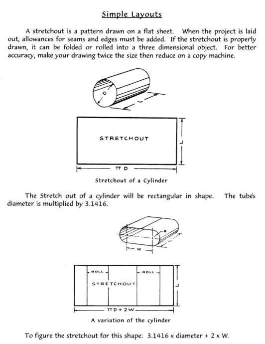 .
. .
.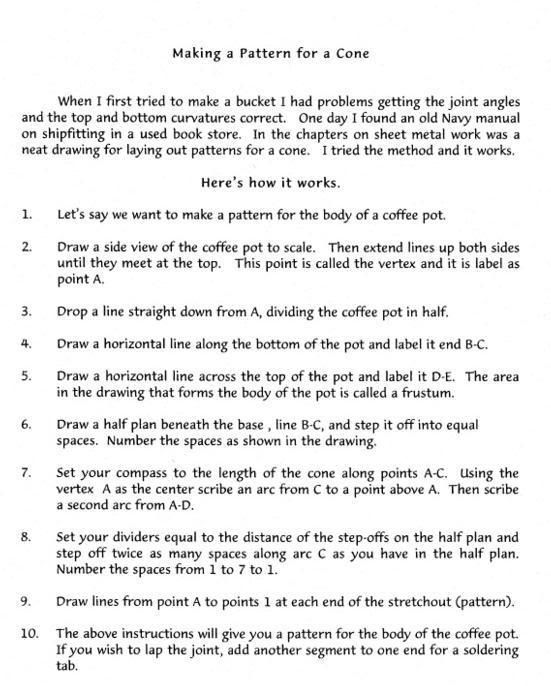 .
.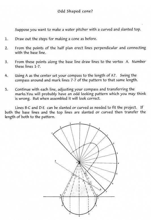 .
. .
.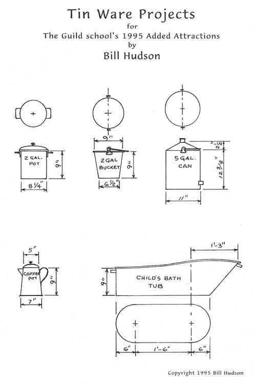
Developing good paper/card patterns and models before fabricating metal is a good way to improve your success at a quality finished project.
I
use carpenter's glue in a puddle so it thickens up a bit. Then apply it with
the sharp tip of a tooth pick. It only takes a few moments to dry.
The photos shown below are of projects that were developed from pattern models.
I had more but they did not survive the packing away and the move.
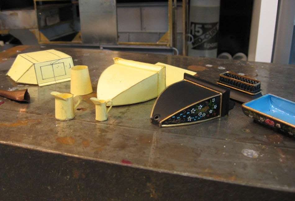 .
.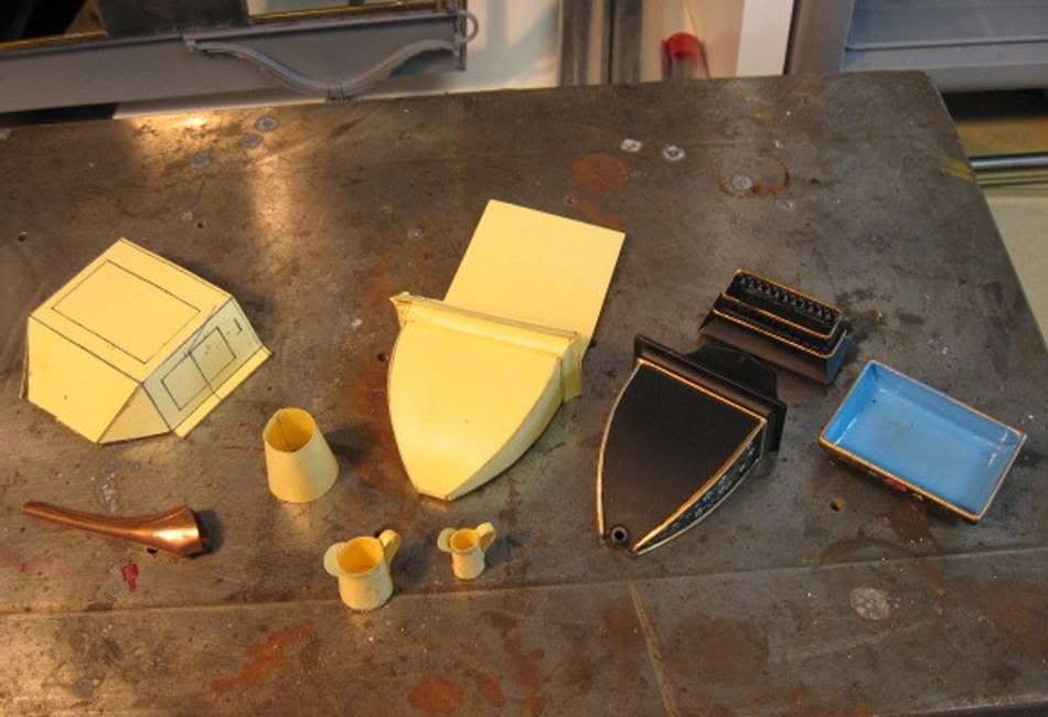 .
. .
.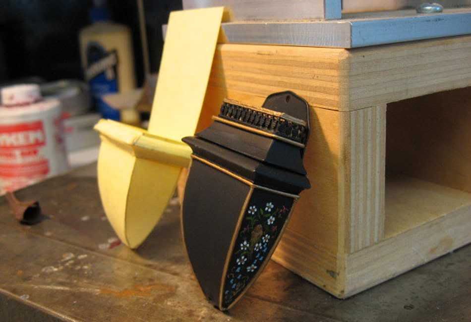
1 and 2. In the foreground, two tin pitchers, the little one one quart (1/12th scale) the larger one, one half gallon. The pint was damaged beyond saving. Also part of a coffee pot and in the background the model for the bay window of the popcorn wagon. The copper piece is a spout for a larger piece.
3 and 4. This is a lavabo (not quite finished). It is a wall hung water vessel with a basin that sits on a table. It is usually used in bedrooms for washing up or shaving but they are also used in kitchens as drinking water and washing up. Some thing similar to a lavabo was some times carried in wagons or chuck wagons while stopped for a night. They held drinking water to prevent contamination of the water barrels by dipping.
I am showing the lavabo because it required developing compound curves for the moldings. The problems in developing the lavabo was made easier by using paper patterns.
Materials
for making tinware.
Most of the material used for tinware is of course tin. That is ferrostan tinplate
or dairy tin now days called tinplate or just plain tin. I was able to purchase
a lot of 5’x5’ sheets of dairy tin about ten years ago and have barely made
a dent in it. The 4” x 10” sheets of tin available at hobby stores packaged
by KS is ok but hard and has a tendency to kink as it is rolled. If that is
all available to you there are ways to overcome that problem (to be discussed
later).
The most available and workable size is .010” thick. This applies to brass and
copper too. It is very close to scale in both 1/12th and 1/8th scale; anything heavier than that
is just too hard to work in small sizes. Brass is also nice and fun to work.
You have to be very careful with your soldering as it shows if you use too much
solder. Brass polishes up nicely or can be darkened. Copper is nice to work
too but slightly stubborn to solder. Very soft tooling copper can be used with
tin for making spouts and small tube shapes and it can be tinned, (a soldering
term).
Tools
Following is an assortment
of tools that I use in my tinware work.
1. Used for bending. The vise-grip contraption is a mini box break I made. Just clamp a couple of like steel strips in the jaws. It is best to place a 1/16" metal strip between the back of the two metal strips. This allows for a variety of thickness to be bent. The rusty large tool is a tinsmiths bending tool. The plastic handled pliers are square nosed pliers with no serration to mar the metal. The silver pliers are clock makers pliers for tweaking pendulum wires. Very good for bending handles etc.
2. This is a combo shear, break and roll. It is made in China so is probably available in most any country. Great shear for small metals. Worth for that part alone. The break is lousy for thin metals and the rolls are great for wagon tires but not anything smaller than 2" diameter.
3. Surprisingly this break works well. Also China made and usually a very affordable price
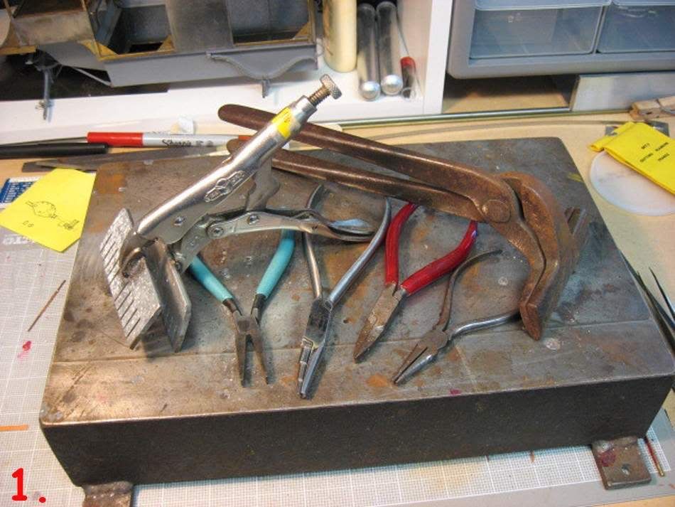 .
.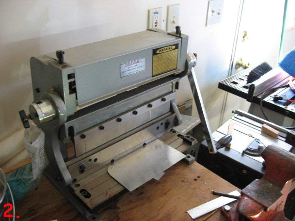 .
.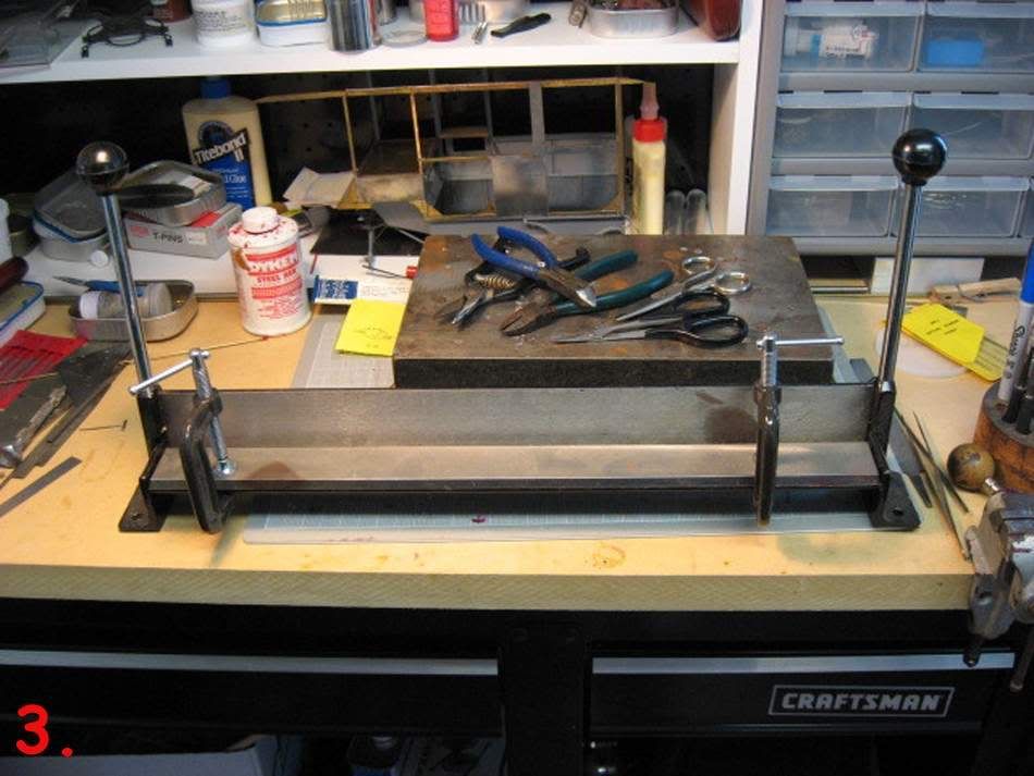
4. Free hand cutting. The blue and green are flush cutters for model rail road track. They work well on brass, plastic, nickel strips but not too well on steel. the spring loaded shears are from a hobby catalog Micro-Mark and are probably something like them at hobby stores. The stainless scissors are telephone wire splicer's shears, given to me by my father in law. The little ones in front with the black loop handles are my favorite. This came from our local hobby shop. They are for cutting plastic radio control car bodies but work great on tin and brass of .010 or thinner thickness. I have been using this pair for over ten years. (they are great for toe nails too!)
5. Hammers.
6.Anvils and formers.
7. More forming tools. As you can see most of my tools are not of the expensive type and most are home made. The wood blocks are for forming concave discs or the likes. Good for pot lids. The blocks are rock maple and most of the end grain is used. Just draw a circle on it and use a power tool and a round burr to form the dish in the wood. Then finish off with sand paper on the tip of your finger.
Left
click on any image to get an enlarged view.
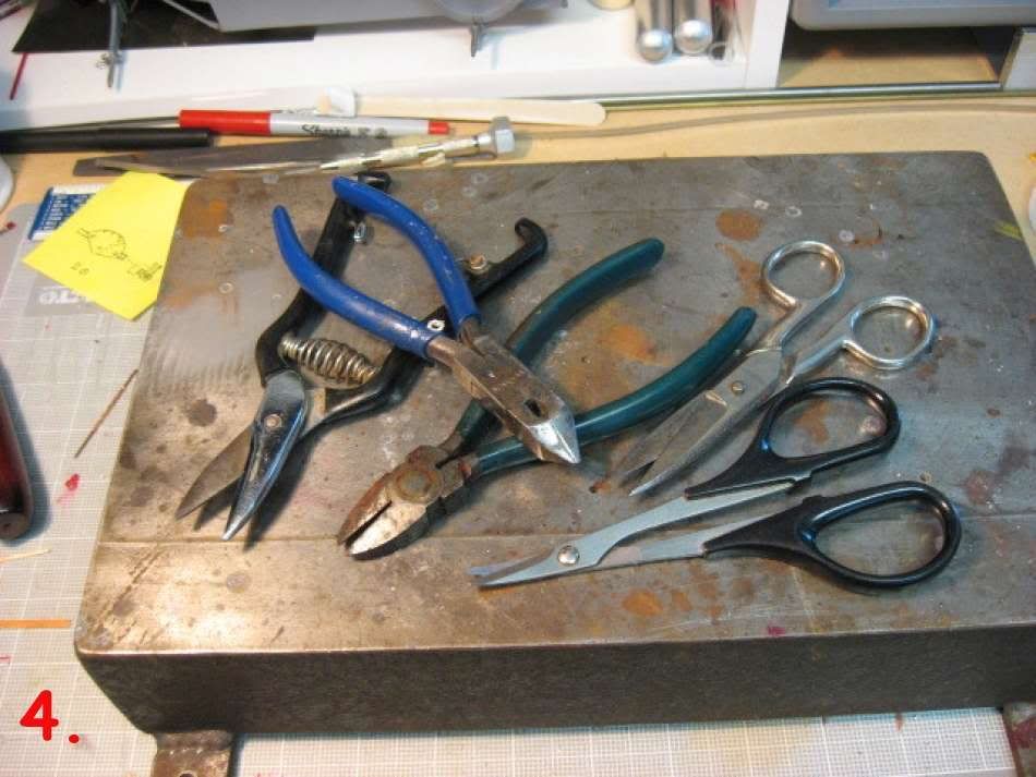 .
.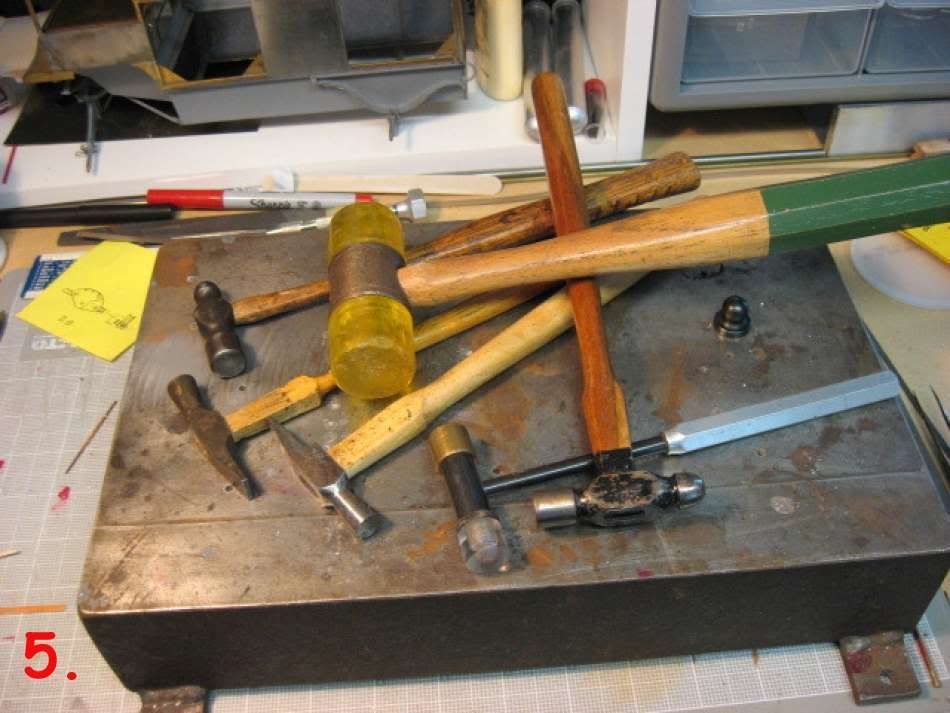 .
.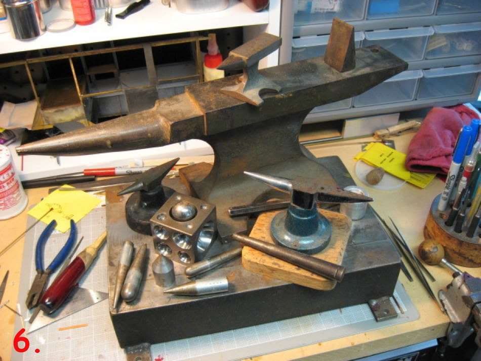 .
.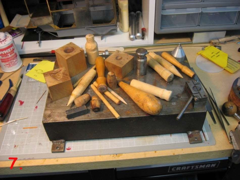
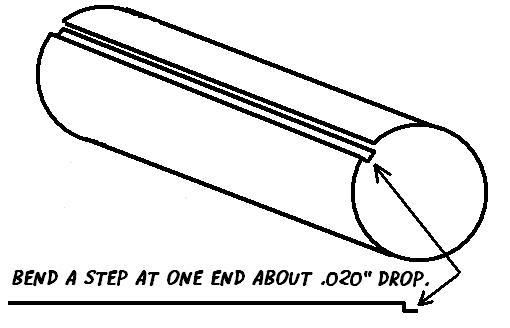 Making
a joint in a cylinder or cone.
Making
a joint in a cylinder or cone.
A simple (brake) bending tool can be made from a but 2" hinge. File or
grind the long edges of the hinge back to 60º angles. This allows making
sharp bends. You can hold this in your hands for bending.
Add 1/8" to
the length of the cylinder or cone to make a tab to make a joint. before rolling
the cylinder bend a step in one end.Bend the whole tab down 90º and then
bend part of it (about 1/32" or less) back to 90º forming a step.
After the step is formed cut off half of the long end of the step leaving about
1/16" or as little as 1/32" length.
Rolling
a cylinder.
For rolling miniature cylinders out of thin metals I like to use a web belt
material or leather belt material about 1 1/2” wide and 1’ long. Clamp one end
in a vise about waist high. lay the cut cylinder metal, with seam leg already
bent, on the belting about six inches from the vise. The step leg end should
be facing you with the leg up. Using a six inch long dowel, undersize for the
diameter of the cylinder,(with ends rounded off for comfort) lay ing it across
the metal right at the leg. I usually hold the loose end of the belt with one
hand whole setting up the dowel with the other. Now let go of the loose end
and using both hands and thumbs pull the belting tight while pinching the metal
tightly against the dowel. Keeping the belt taught roll you hands forward while
dropping them down. Once you have reached bottom move back up and re-grip starting
the process again until the cylinder is rolled. Roll the ends pass each other
with the plain end on top. When done you should ba able to spring the cylinder
open so that the plain end will snap into the step.
Note
on rolling tin.
The reason for using a web strap or leather belt for rolling cylinders it to
eliminate the tendency of tin to kink every little bit as it is being rolled.
Very small pinch rolls (ones that pinch the metal between them as they roll
are very hard to find. This type is less likely to kink the tin. The type that
uses a top roll to press the metal down between two lower rolls is the worse
for kinking. By using a strap you are supporting and backing the metal with
the strap, which helps stop some of the kinking if you are lucky and keep enough
pressure on the metal with your thumbs.
Planishing
out cylinders and cone bodies.
It is inevitable that during your rolling and bending you get some lines or
kinks in the bodies. Look back at the tools. You will see a variety of anvils
and round bars (mandrels or dollies as they are also know by), some tapered.
Most of the work can be done on the shiny jeweler’s anvil but you will also
find an assortment of home made bars useful too. In removing dents and kinks
place the cylinder over the rounded end of the anvil and using a plastic or
brass hammer tap them out. Use a glancing blow. For finish you can use a planishing
hammer. You can buy an expensive jewelers hammer or use an inexpensive 2 oz
ball peen hammer and polish up the flat end to a smooth shiny dome.
Truing
up and rounding.
It is likely, that when you have got to this stage, you will end up with an
egg shaped cylinder rather than round. Notice in tools there are several dollies
of different tapers. Place one in the end of the cylinder and lightly tap on
it. It will round out the cylinder. Flip the cylinder over and do the other
end. The tapered bar’s, are good for cones like coffee pots and buckets. You
can make wood or metal dollies to fit the inside of you bucket or coffee pot
and tap them to final shape.
Making
spouts.
Some spouts are cylindrical and others are tapered. For cylinder types use available
brass tubing. Even so I like to chuck it in a lathe or drill press and file
it to a slight taper. It just looks better. For taper spouts, use a soft tooling
copper. Wrap it around a tapered mandrel. To make a mandrel, use a 3” long piece
of 3/16” round steel chuck it in a lathe or drill press and turn or file it
in to a very long taper down to a fine point.
_files/Spout.jpg)
To
make a mold board for the spouts.
Clamp two hard wood blocks together, tilt the block about ten or fifteen degrees;
in a drill press and with a 3/16” bit drill down the length of the block. As
you drill, the drill bit should start centered at the joint and as it drills
down it should cross the joint line and end up coming out at the bottom on the
side of the line. When opened you should have a tapered hole from one end to
the other.
Forming
the spout.
Cut you spout out using a pattern and lay the flat spout along the mold. Press
the mandrel down into the metal, forming it to the mold. Bend the rest of the
spout over the mandrel and tap it down on the mandrel forming the joint. Remove
the spout and coat it with flux and tin the whole thing.
Wiring.
To strengthen and finish off tin ware the edges are wired. That is you will
see that the top edge of a bucket is rounded off. This is done by wrapping the
edge around a wire. That is nearly impossible in miniature. I use wire, just
plain brass beading wire. I tine the wire, wrap it a couple times around a smaller
dowel to form a ring and then solder the ring on the top edge of the bucket.
It is that simple. Well not quite!
Using a couple of feet of 26 gauge brass beading wire clamp one end in a vise, grab the other end with pliers and pull on it, stretching the wire a couple of inches. This straightens out the wire and hardens it. Then flux the wire and tin it. Wrap the wire around a smaller dowel than the diameter you need. Make several rings; wrap the ring around the top of the bucket so that the joint mates up with the bucket seam. Tack the wire in place in several places. Lay it top side down on the soldering block or a smooth block of hard wood and run a solder fillet around the bottom side of the wire. When you turn the bucket backup run your iron around the wire and bucket joint. This will draw the solder up. Finish off with a file. ~Bill Hudson.~
_files/sippintin.jpg)
_files/potmugs.jpg) Remember,
Practice. Practice and more practice
.
Remember,
Practice. Practice and more practice
.
This ends the tin tutorial. I hope it is of value to you all.
To link to this tutorial as it first appeared in the forum in October 2007- Click HERE.
![]()
Visit my new updated chat forum
_files/Wagon%20Wheel.jpg)
![]()
_files/squareround.jpg)
_files/solderstrip.jpg)
_files/finished.jpg)